Building From Plans – Part 4
Building the Rotating Printing Press
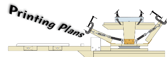
Step 14: Now that you’ve secured the brackets (H), you can use them to hold each arm (T) in place while you do the next step. On each arm, draw a line 1 5/16” in from the outer edge of part T (see fig. x). Using these as guides, screw in each of your 1/4″ lag eye screws into parts T until they only stick out about 2 1/4” from the board. Next screw in your set of four smaller lag eye screws into part B, halfway between the bolts that are already on the dotted line and parts S. See fig. x for the proper orientation of the lag eye screws. Now gather all your springs and turnbuckles. You’re now going to connect one spring to the closed end of each turnbuckle. If the ends of the springs are closed instead of hooks, clamp one pair of vise grips onto the end of a spring as indicated by the red bar in fig. y. Next use your other pair of vise grips and grasp the same end of the spring as indicated by the blue bar. Now as you bring the two pairs of vise grips together it will widen the opening. Once the opening is wide enough, remove the vise grips and attach the spring to the eye end of the turnbuckle. Now use a single pair of vise grips to sqeeze the openings on the end of the springs closed. Do this to all 8 sets of springs and turnbuckles (see fig. y).

Step 15: Now attach each of your turnbuckle/spring combos to the top rotating mechanism. The hooks will attach to the large lag eye screws at ends of the arms, and the loose ends of the springs will attach to the lag eye screws sticking out of the octoganal part B (two springs per lag screw). You’ll need to use the vise grips to attach the springs as before. We’ll adjust the tension of the turnbuckles later on. You can push each arm down so it touches the table to keep it out of the way while you work. Now take each of your C-clamps and drill a hole in the the main arm 1” up from the the point shown in fig. aa. [Clamp shown is a 2.5“ clamp. You can use 2” clamps just as effectively.] This hole should be just slightly smaller than one of your screw heads. After you’ve done this to all eight, weld your 1” or 1 1/4” diameter washers to the mobile part of the clamp as shown. Welding glue will work just fine. Put cardboard in between the washer and the adjacent part of the clamp to avoid bonding the clamp to itself. The purpose of these washers is to create a greater surface area on the clamp so as to avoid denting your screen frames.

Step 16: (Note: Fig bb shows what to do with 2” clamps, fig. cc with 2.5” clamps.) Once the welding glue dries, and using figs. bb (or cc) and dd as your guides, screw your altered C-clamps through parts X into part T. (You’ll want to have parts X glued and clamped to make this easier.) The washers that you welded onto the C-clamps need to clear the side of the vertical part of bracket J. The bottom of the C-clamps can be welded (glued) underneath brackets J as shown in fig cc., but this is optional. Tighten the clamps all the way while you work and while it glues to help hold them in place. Not only will your C-clamps hold your screens firmly in place, but they will also act as a place to rest your squeegees when your screens are in an upright position.

Step 17: Part R-a has a notch on the top, part R-b has a notch on the bottom. Glue part R-b onto part R-a so the notches intersect, forming an “X”. Attach this “X” onto the top of parts S so that it is centered, as shown in figs. ee and ff.

Step 18: Next attach shelf C onto the top so that the corners are each in the middle of parts R (see fig. gg). Now sand off the corners protruding from parts Q and U. Not only will this save you some potential pain as you print, but the smooth end of the platen arm will help shirts slide on more easily.
20” x 24” frames work best with this press. Attach a frame to each arm (one at a time) and place a squeegee on it. Now that you’ve got it at its operation weight, it’s time to adjust the turnbuckles so it will gently return back to the upright position in between pulls (if released about half way up). For each arm, make sure you adjust the two turnbuckles equally until you are happy with the tension. If your press squeaks when the arms are lowered, use a little WD40 on the insides of parts H. That’s it. You’re done! Happy printing!

Part 1: Build From Plans - Part 1
Part 2: Build From Plans - Part 2
Part 3: Build From Plans - Part 3
Part 4: Build From Plans - Part 4