Build From Plans – Part 3
Building the Rotating Printing Press:
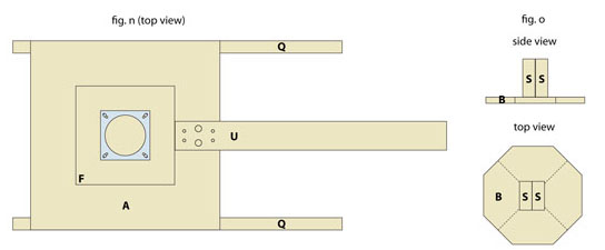
Step 9: Attach your “Lazy Susan Turntable” directly in the middle of part F using 4 of your 1 3/4″ hex cap bolts. Drill holes directly through parts F and A to do this and use hex nuts to secure them underneath. Fig. n shows this as if the top part of the turntable is missing, just so you can see the orientation of the hex cap bolts. Draw an X onto part B by dividing it in half and in half again. Make sure this is exactly in the center. You’ll be using this later. Next glue both parts S back to back and attach the end of the resulting block to the middle of part B. See fig. o for two views of this.

Step 10: Your accuracy in the following steps is vital to the success of your finished product, so measure carefully! Drill holes in each of your metal brackets as shown in fig. p. Now use a larger bit equal to the size of your screw heads and drill in each of your holes, so that when you screw the bracket on, the screw heads will be flush. Attach each bracket to the end of a part T, making sure it’s in the exact middle from side to side. The vertical position of the bracket depends on the width of your coated lumber (used for the platen). If you are using 3/4” thick wood for your platen, the bracket should extend past the bottom of part T the thickness of your hinge. (fig. q). If you are using 5/8” thick wood for your platen, place the brackets an ADDITIONAL 1/8” down past part T. On the opposite end of each part T, screw in one of the hinges so that the edge of the cylindrical part of the hinge is flush with the edge of board T. Use the screws that came with the hinge. The hinge should be facing “up”, so that when you put in the screws from the bottom into the wood, it will be through the “wrong” end. In other words, the tapered part of the hole is now between the hinge and the wood, and the larger part of the cylindrical section of the hinge is facing up (figs. q & r).

Step 11: Now attach each arm (part T with additions) to four sides of part B using the rest of the screws that came with the hinges (fig. s). Make sure that “length y” is the same for all arms. Using the “X” you drew onto part B in step 9, measure in 2 1/4” from each side and drill a hole big enough for your 3/16″ hex cap bolts.

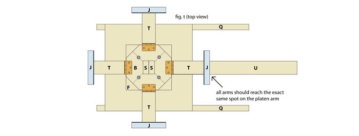
Step 12: Bolt the piece you just built in step 11 to the lazy suzan turntable using 1/4″ hex cap bolts from underneath and the appropriate nuts and washers.. Make sure all four arms reach the exact same spot on the platen arm (as shown in fig. t). You can probably move the whole top part slightly until this is the case, and then tighten the nuts. If you can’t seem to get each arm to the same spot on part U, tighten the nuts when you’ve done the best you can. You still need to get the arms the same length, so mark the shortest one, remove part J from any arm that is longer, and sand part T until it’s the appropriate length. Now reattach any part J that was removed. This may seem like a lot of extra work, but it will be well worth it once you start printing multi-color shirts.

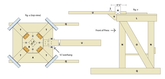
Step 13: Twist the top mechanism 45° to get it out of the way (this will become easier when we add the springs so the arms will be out of the way). If it won’t twist because it binds on part U, sand enough of the inner end of part U off until there is no obstruction. Attach part I onto the platen arm (U) using a single screw (otherwise it would probably split). It should be right where part J lands when you lay an arm onto part U, or about 8 5/8” in from the inner end of part U (see figs. u and v). Next attach parts H to the platen arm (part U) so that the curved part of the board is on top and faces in, and so that parts H overhang 7/8” over the side of part A. Make sure to predrill holes for the screws (slightly small than the screws) to make this easier. See figs. u, v and w for different views of this.

Step 13 (continued): Fig. w shows boards H with the curved parts facing in. The reason for this is that as you lower an arm into place, the curved edges will help it fall easily into place. Try doing this now to make sure there is the correct width between the two parts H. The arm (T) should fit VERY snuggly, but stil be able to go into place without excessive force. Remember that when you have a screen connected to the arm it will become even easier to do this because of leverage. Getting parts H to be the perfect distance apart was one of the most difficult parts of building my own press. At first it was too tight and required some adjustment. To make these fine adjustments, loosen the screws and use pieces of cardstock as shims in between parts H and U. Then retighten the screws. Add more shims as necessary until you have the perfect width. If you take the time to do this, you’re press will be ultra-accurate.

Part 1: Build From Plans - Part 1
Part 2: Build From Plans - Part 2
Part 3: Build From Plans - Part 3
Part 4: Build From Plans - Part 4
